I only flew a few moments, but man that was sweet. Unfortunately the camera stopped recording so my follow up flight didn’t stick. I was also flying on the yard and at close to sundown so I didn’t feel like pushing it further.
Hopefully I will soon have a lot more videos to post.
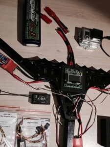
It’s all coming together! I had a little trouble there for a moment. Before flashing SimonK bs I couldn’t get my ESCs to fire up. I was probably doing something wrong but hey, I was going to flash the ESCs anyway. I use the KKflashtool on Linux with my 9X usbasp and the “HK atmel chip piggyback adapter tool”. Also showing in the beginning is my “FrankenCable” or HXT to JST adapter, connected to a “USBpower to header-pins “-cable fed with a 5V/1A poweradapter.
Tomorrow I hope to get some more stuff crossed off! Especially the servo for the motortilt… TBC…
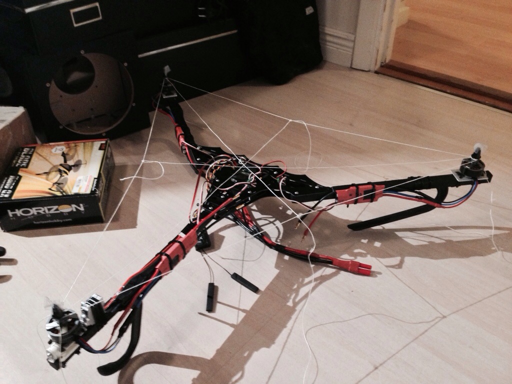
Well things are coming together nicely. I finished attaching the last bulletconnectors (18!! solderings) needed for flight capable electrical system this Sunday. I still have a loooong list of things to be done but figured it was time to lay out all the parts to get a feel for how it will look and also a first notion as to how I will be able to route the cables. It looks as I will not need the extension cables for the ESCs after all, length of ESCs cables with connectors should suffice. Next up will probably be attaching the servo for the tilt. After that testing the ESCs and motors, reading up on SimonK programming ESCs then do that and also prepare by researching on setting up the KK2.0. and … tbc… 😉
Quick update! I had some hobby paint at home and since I already did file down the wood earlier after the sawing and I had the time – I went for it. Possibly the easiest step so far, painting the arms. I like to work with wood as a material. Much more pleasant than aluminum. Hey look another use of my Dremel workstation! Yey!
After visiting about 4 hardware stores in search of what I thought was a relatively common dimension I finally found them at a local hobbyshop I didn’t even know existed: ReservdelsRC. Went there yesterday and when entering the shop and looking around I saw their “Great Wall Of Screws And RC Accessories”, wow! Jackpot! I could even choose between two different materials and designs. Also, my calculations on screwlength will work. I got 20pcs M3x6mm and also just in case 20pcs of M3x8mm. Later I might also buy som extra M3x20mm’s for the Bat Bone.
And yes I will probably do 1000 posts before this Tricopter flies 😛
So I finally got to sawing the sticks into arms. With my dremel the once forseen problem with using 14x14mm sticks instead of 12.8×12.8mm soon vanished. As you can see in the images below I carved it down on one side and it is a perfect fit, somewhere around 13x14mm. I also drilled the holes using the Dremel with workstation. I managed to put the two in the back arm in pretty much perfect center and aligned with the bat bone (not done yet in the picture). It seemed impossible at first, especially since I had moved my support bits that held the wood in place. Managed to align and with careful testing and tiny corrections I got it. I’m not even sure if I can replicate that ever again. So I hope they never break…
So here is the first picture of how large it will become once built. Even though there’s still much to do this milestone felt so good. 🙂
Yey! It can has propellers! Lolz! My cat felt I needed her in the picture for size comparison. She is quite a sturdy cat though 😉
I found some new material for the motormounts! A piece of silver-anodized aluminum. It was abit expensive at $11 or 75kr, considering I will be using only ~15cm of the total meter length. But hey, at least now I’ll have spare material incase I need to make repairs.
So I have begun working on the final product. I have some drilling to do, it should be easy enough.
So here is the final prototype for my motormount.
I might have used the wrong bit for the Dremel. I used a carving bit for engraving but should have tried the cutting bit first. Now I had to do layer by layer like 20passes for each cut. Maybe I don’t need to do that if the cutting bit works with this plastic… I’ll try that next time.
So I have an idea on how to build some motormounts for the AX2810Q (16x19mm cross) to attach with zipties to my wooden booms. I also found other examples on people executing that idea. But using materials and methods of manufacturing that I don’t have access to. I will however try out this thing anyway. By prototyping my way forward from what I began with and created this evening, in cardboard. Needless to say, I will use a somewhat more rigid material in the finished product ;-). Here’s a pic on what this process looks like right now.
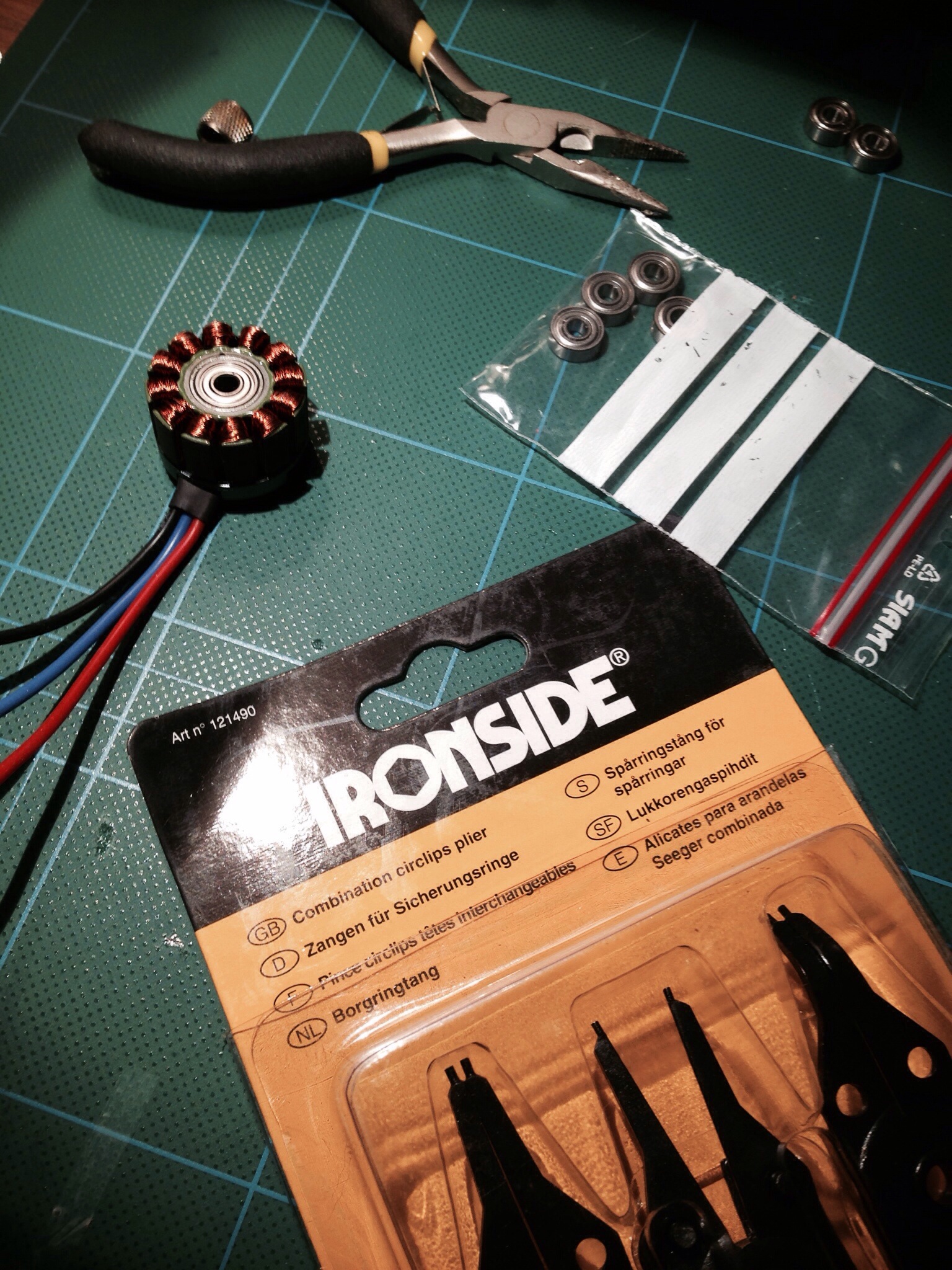
Bearings upgrade
I also bought the kind of pliers needed to disassemble the motors today… hmm…).
Unfortunately I was only successful in replacing the two bearings of one motor. The others where totally stuck and so wouldn’t budge. I gave up. Thinking a broken motor is worse than a bad- or “prone to break and get bad”-motor. I also found something weird stuck in the casing around the magnets… Possibly something that should be left there, maybe for balancing? Some brown/black solidified paste or sediment. I didn’t feel like scraping that off. What if I break the balance? I also found out that there’s abit of oxidation, as you can see in pictures below.
But I’m not sure that’s a problem either. Perhaps it’ll burn off or something when I run the motors hot (which I shouldn’t do)…
Motor-tilt-hinge
I almost forgot that I think I managed to assemble a working hinge for the tilt mechanism yesterday night. Not as pretty as David’s carbon fiber axeled but I had a screw that fitted nicely. Locally available parts precede fancy materials if they are good enough. 🙂 Here it is!